
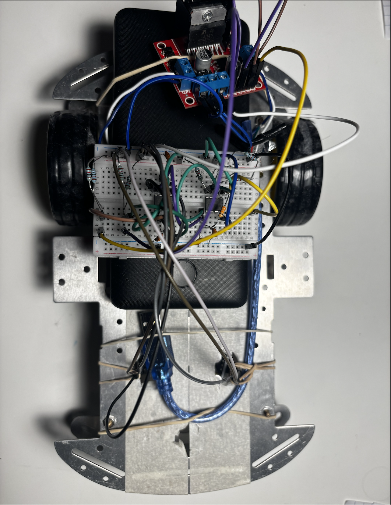
An opamp-driven line following car
Motivations
In our ECSE 200 lecture, Prof. Marwan mentioned towards the end of the semester the ability of opamps to perform integrals and derivatives. I immediately thought about the classical PID (proportional - integrative - derivative) algorithm and was curious about implementing a hardware level PID.
Doing so removes the extra overhead of software used in microcontroler boards, like an arduino for example. The feedback correction can thus be pushed to higher response rate, with the LM393’s small propagation delay of <1μs.
I also wanted to see if I could design such a circuit using entry-level, cheapest opamps I could find online. For the Schmidt trigger circuit, I went for a LM358P dual-opamp.
Criteria for opamps
- I wanted an opamp whose sweep range could go down to GND. In a previous experiment with precision opamps to make a PWM generator the output couldn’t go below 2V unless I applied a negative voltage at the opamp’s negative power rail. The LM393[1] satisfies those conditions when used in open loop comparator (Common-mode input voltage range includes ground).
Implementation
I inspired myself from a circuit template found on everycircuit.com .[2]
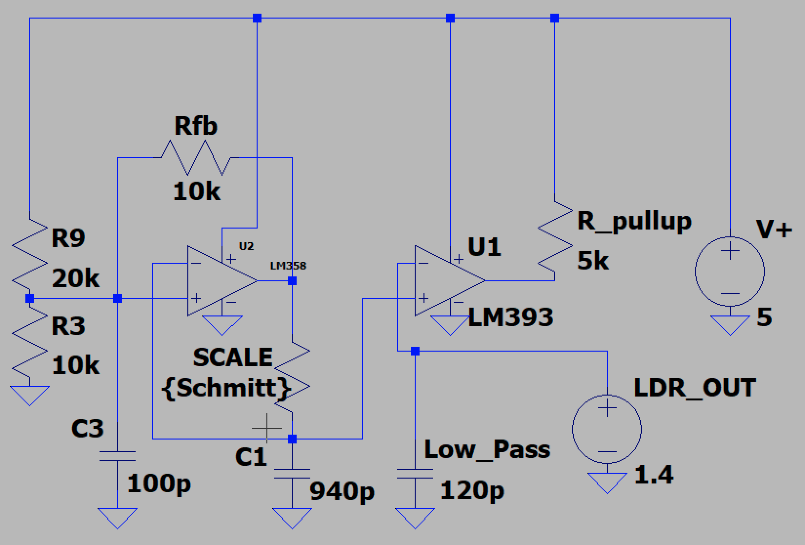
For now, the inverting input of the LM393 is connected to the digital output of an LDR module. Later, I will try to read the raw analog voltage of the IR receiver and setup a voltage divider to scale the output voltage. This will add more precision and help the robot generalize without having to tweak the LDR’s onboard 10k potentiometer
For later
- Implement a full PID robot (right now I merely did a Proportional response)
- Use analog reading from LDR instead of digital levels.
- ← Previous
Another way to see the comp 206 homework